CWC610000 series temperature sensor
2021年1月15日
CYB3700 series flange pressure transmitters
2021年1月19日


CYB1800 series differential pressure transmitter
1 Product introduction
CYB1800 series product is a small-profile differential pressure transmitter. This series of products use high-reliability silicon piezoresistive differential pressure sensors as the core components, and output standard industrial signals after temperature compensation, digital circuit correction and signal conditioning. Each type of product has undergone careful design, component screening, process verification and curing, cyclic loading and aging, environmental simulation testing and other processes to ensure that each product is stable and reliable.
2 Features
◆compact size, easy to install
◆high stability, low drift
◆a variety of structures to choose from
◆it can be used in industrial occasions
3 Main uses
The CYB1800 series differential pressure transmitter is widely used in various pressure differential measurement due to its excellent accuracy and reliability. Especially in coal mine, oil field, chemical industry, civil explosion, environmental protection, medicine, water affairs, shipping and other industries, Huatian brand pressure transmitters have been widely recognized by customers.
4 Technical index
|
range |
MPa |
-0.1MPa…0kPa~10kPa…3.5MPa |
||
|
pressure form |
D |
|||
|
level of accuracy |
0.1(customized) |
0.25 |
0.5 |
|
|
nonlinearity(FS%) |
≤0.1 |
≤0.2 |
≤0.4 |
|
|
hysteresis, repeatability (FS%) |
≤0.05 |
≤0.05 |
≤0.1 |
|
|
zero point and sensitivity temperature drift (%FS/℃) |
≤0.015 |
≤0.03 |
≤0.05 |
|
|
long-term stability (%FS/year) |
≤0.1 |
≤0.2 |
≤0.5 |
|
|
operating voltage (VDC) |
+10~+30( calibration value is +24) |
|||
|
output signal |
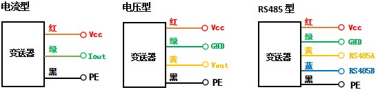
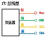
4mA~20mA、0~10V、RS485、I2C bus type |
|||
|
compensation temperature (℃) |
0~+50(≤200kPa),-10~60(>200kPa) |
|||
|
operating temperature (℃) |
-30~+60 |
|||
|
overload capacity (%) |
≤200 |
|||
|
overload capacity (Ω) (4mA~20mA) |
R=(U-12.5)/0.02-RD among them: U is the power supply voltage RD is the internal resistance of the cable |
|||
|
response time (10%~90%)ms |
≤1 |
|||
|
measuring medium |
fluid compatible with 304 and 316L |
|||
|
diaphragm material |
316L |
|||
|
shell material |
304, 316L/aluminum alloy |
|||
|
interface |
304, 316L optional |
|||
|
protection level |
IP65( customizable IP67) |
|||
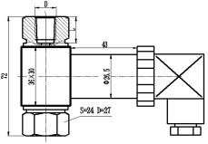
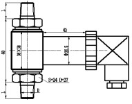
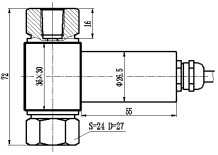
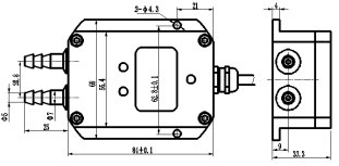
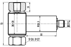
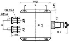
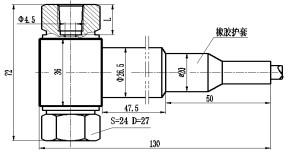
5 Transmitter size
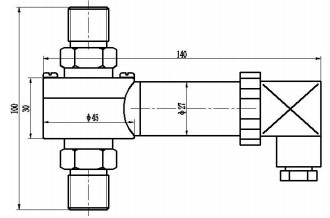
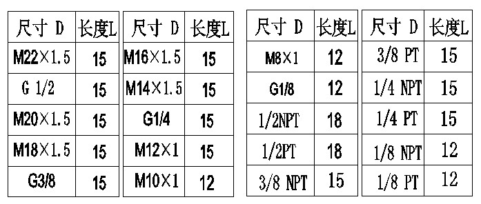
recommended optional connector size for CYB1800 series
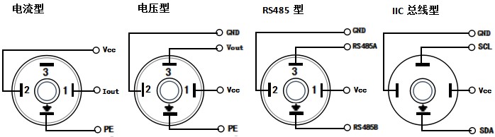
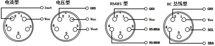
6 Electrical connections
6.1 Horsman socket
6.2 Aviation socket
6.3 Direct cable outlet
7 Order guide
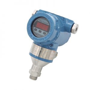
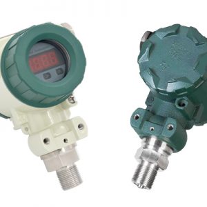
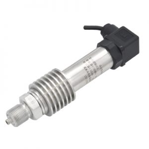
7.1 Model characteristics and appearance
|
Horsman connector |
||
|
model |
features |
pattern |
|
CYB1810 |
1. Standard integrated Horsman connector; 2. The full range of recommended threads is optional; 3. The pressure interface material can be customized; 4. Protection grade IP65. |
|
|
CYB1811 |
1. Housing combined with Horsman connector; 2. The recommended series of threads are optional; 3. The pressure interface material can be customized; 4. Protection grade IP65. |
|
|
Waterproof connector |
||
|
CYB1820 |
1. Standard integrated waterproof connector; 2. The recommended series of threads are optional; 3. The pressure interface material can be customized; 4. Protection grade IP65. |
|
|
CYB1828 |
1. Non-corrosive dry gas measurement; 2. The recommended series of threads are optional; 3. The pressure interface material can be customized; 4. 4-digit LCD display |
|
|
Aviation connector |
||
|
CYB1830 |
1. Standard integrated aviation connector; 2. The full range of ranges, the recommended series of threads are optional; 3. The pressure interface material can be customized; 4. Protection grade IP65. |
|
|
CYB1835 |
1. Non-corrosive dry gas measurement; 2. The full range of ranges, the recommended series of threads are optional; 3. The pressure interface material can be customized; 4. Square shell. |
|
|
Level outlet |
||
|
CYB1841 |
1. Waterproof liquid level outlet, waterproof grade IP68; 2. Flat membrane structure, easy to clean; 3. The pressure interface M20×1.5, G1/2 is optional. |
|
|
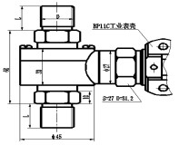
CYB1863 |
1. BP11 industrial housing; 2. Pressure port M20×1.5 or G1/2; 3. Waterproof grade IP68. |
|
7.2 Selection Guide
|
CYB18X3X4 |
differential pressure transmitter |
||||||||||||
|
|
range |
measuring range -0.1MPa…0MPa~0.01MPa…3.5MPa |
|||||||||||
|
xxn |
the unit is kPa. The first two digits of XX are multiplied by 10, and N is the third digit. |
||||||||||||
|
|
|
code name |
pressure form |
||||||||||
|
D |
differential pressure type |
||||||||||||
|
|
|
code name |
supply voltage |
||||||||||
|
U1 |
24VDC |
||||||||||||
|
U2 |
12VDC |
||||||||||||
|
U5 |
other power supply methods |
||||||||||||
|
|
|
code name |
output signal |
||||||||||
|
E1 |
4mA~20mADC |
||||||||||||
|
V3 |
0VDC~10VDC |
||||||||||||
|
V5 |
other voltage output |
||||||||||||
|
R4 |
RS485 communication Interface |
||||||||||||
|
H |
HART® protocol communication |
||||||||||||
|
Ⅱ |
I2C protocol communication |
||||||||||||
|
|
|
code name |
shape interface |
||||||||||
|
electrical Interface |
mechanical interface |
||||||||||||
|
Horsman socket (J1) |
G¼ |
||||||||||||
|
Aviation socket (J2) |
G½ |
||||||||||||
|
Waterproof connector (J3) |
G1 |
||||||||||||
|
Liquid level outlet (J4) |
M20×1.5 |
||||||||||||
|
others(J5) |
othes( Direct label ) |
||||||||||||
|
|
code name |
Direct label |
|||||||||||
|
M1 |
4-digit LCD digital display meter (only 4mA~20mADC output) |
||||||||||||
|
M2 |
4-digit LED digital display header (only 4mA~20mADC output) |
||||||||||||
|
d |
flameproof ExdⅡCT5 |
||||||||||||
|
i |
intrinsically safe explosion-proof type ExiaⅡCT6 |
||||||||||||
|
QT |
other functions |
||||||||||||
|
CYB1811 [102] D U1 V3 J1G½ complete model specifications |
|||||||||||||
Ordering model CYB181 [102] D U1 V3 J1G½ indicates the product model CYX1811, measuring range 1MPa, differential pressure, 24V power supply, 0~10V output, Horsman connector, G1/2 threaded connector.
8 Precautions
8.1 When the product range is within -5~5kPa, the sensor uses a non-isolated silicon piezoresistive differential pressure chip, and the product can only measure non-corrosive gases.
8.2 When the product is at risk of being immersed or submerged, please order the liquid level outlet type, or consult.
8.3 The installation interfaces on both sides ensure coaxiality to ensure that the transmitter interface is not subject to excessive stress.
8.4 The static pressure needs to be within the range specified by the transmitter.
8.5 Please install a balance valve in a measurement environment that is prone to single overpressure.
8.6 When installing, use a wrench on the six sides of the pressure joint close to the thread. It is forbidden to use the watch case as the focus point to prevent damage to the sealing performance of the product.